Debugging a Ticking Refrigerator
19 November 2017
Over the past few weeks, my refrigerator started making a rhythmic ticking sound, almost like the chugging of a toy train. My instinct was first to wait and see if it would solve itself. It kept getting louder.
Why had it changed? Soon, I had to know.
Moving parts
To my knowledge, the refrigerator had only two moving parts: the compressor and the evaporator fan in the freezer that circulates the cold air. I opened the freezer to check on the fan; all good there. I concluded that it must be the compressor, a worst-case scenario because the compressor is expensive and attached directly to the refrigerant lines throughout the fridge. It would be a hard sell to get the whole fridge replaced just because it was making noise.
My subconscious mulled it over for a week or so (this noise was really getting to me). Something about it wasn’t like the compressor. For one, it was rhythmic, with a totally different period than the compressor noise. Second, I could swear I had heard the ticking sound in the middle of the night, when the compressor wasn’t running at all!
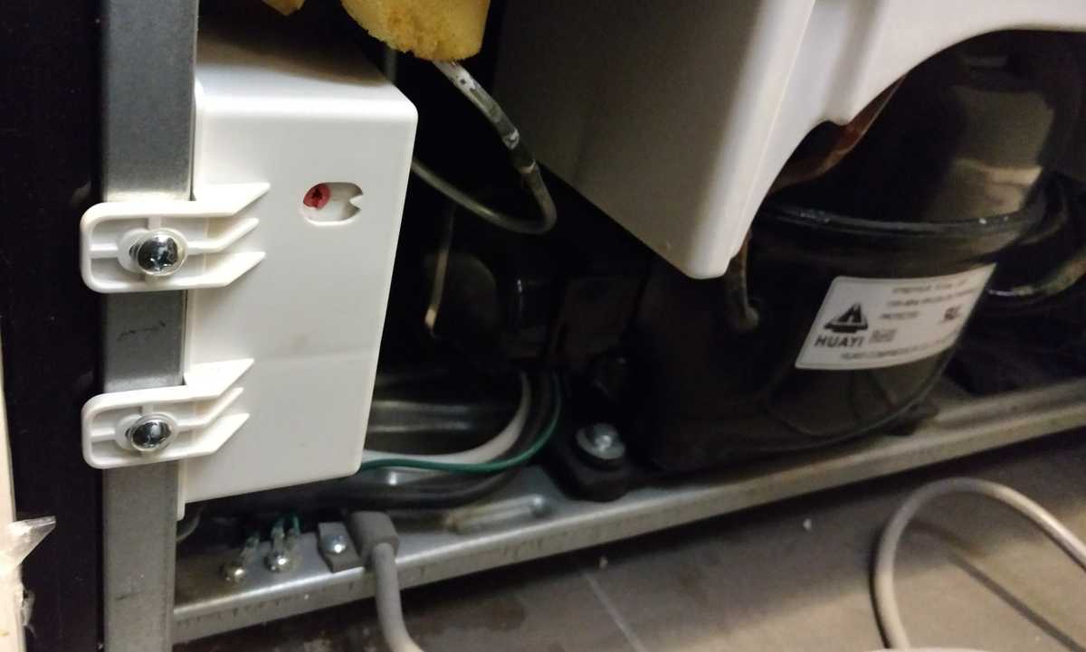
I decided to climb behind the fridge and check it out. Immediately, the source of the ticking revealed itself as a small white box near the compressor. There was hope after all for a cheap fix.
The defrost timer
After some investigation online, I discovered that the ticking box was the defrost timer, responsible for alternating power between the compressor, which manages cooling, and the defrost heater, which melts the ice that accumulates in the freezer around the evaporator fan.
The defrost timer is a marvel of low-cost engineering that I want to take this post to appreciate:
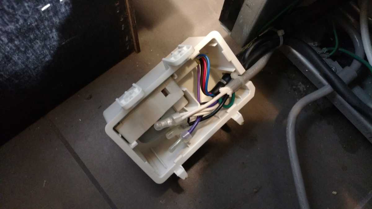
Inside the junction box, you can see the defrost timer. It’s a small synchronous AC motor connected to a plastic gearbox.
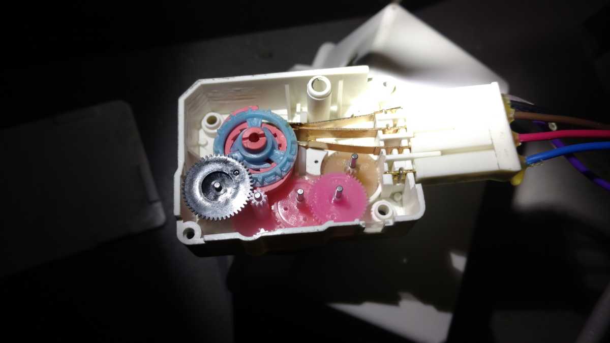
I opened up the gearbox to see if I could find the issue. Here’s the inside:
The gear train
The motor is on the back side of the box in this view, and powers it through a small wheel hidden under the white faring the middle. To the right of the faring, the brown wheel steps down the speed, and so on for the pink wheel to which it connects.
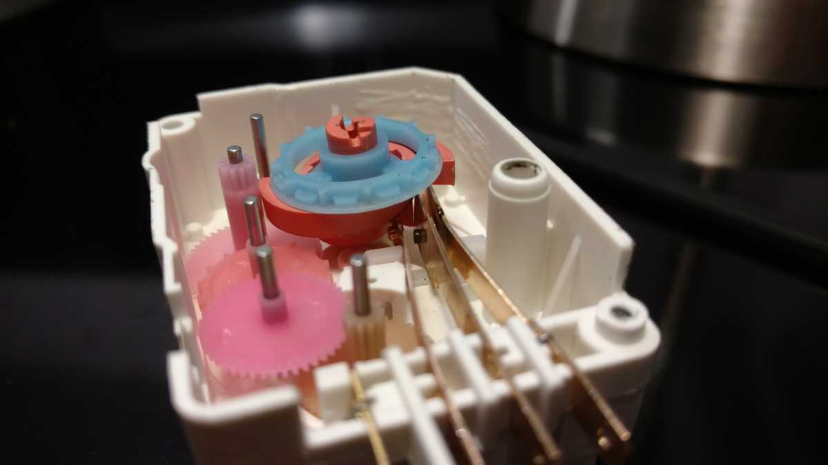
Then, to get even lower speed, that first pink wheel has a form of geneva wheel to connect it to the next. It advances the second pink wheel by one tooth for each of its own rotations. Further reductions through the third pink and the gray wheel ultimately drive the blue wheel through a second geneva mechanism.
The result is that the blue wheel, connected to the pink cam assembly under it, rotates about once every 24 hours. As you can see in the image, it influences the positions of the three electrodes entering from the connector on the right.
Electrical system
The defrost timer doles out power to the compressor and defrost heater in turn. The center electrode is line in, connected to the hot terminal of the wall outlet through the thermostat inside the refrigerator cabinet, which acts as a simple switch. The timer only gets power when the thermostat is closed.
The electrode on the right feeds out directly to the compressor circuit.
The electrode second from the left connects to the defrost heater. The defrost heater only runs when the freezer cabinet temperature is below freezing.
The central pink cam alternately connects the center lead to either of its neighbors. For most of one revolution, the right two electrodes are shorted, meaning the compressor has the option to draw power through the thermostat. For a much smaller part of one revolution, the middle two electrodes are shorted, meaning the defrost heater has the option to draw power.
The lead on the left only connects to the motor… Interesting :)
How does the motor get its power?
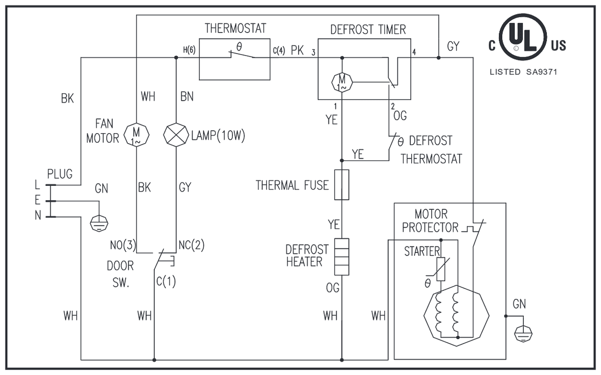
The thing that baffled me about this circuit is where the motor gets its power. Look closely at the terminals entering the box. The silver wires on the leftmost and rightmost drop down to power the motor. So, the motor must be connected to the compressor power line, and to the mysterious leftmost terminal, which the refrigerator schematic confirms leads to the defrost heater’s thermostat:
This schematic is pretty hard to follow, not least because of its “art style,” but props to Frigidaire for making it easy to find on their website.
Since I observed the timer motor running with the compressor and without it, I know it had to be powered even when the compressor is off. The motor gets power in two distinct ways:
- When the compressor is running, the thermostat is closed (connected), and the timer connects line-level power coming in on lead 3 to the compressor via lead 4. In this mode, lead 2 (to the heater) is disconnected by the position of the switch cam. From the schematic, we see that the motor’s only connection to neutral is through the heater! The motor’s impedance is so high compared to that of the heater that it effectively drops all of the potential across it, and ultimately sends a tiny current through the heater to neutral.
- When the heater is running, the timer’s input lead 3 connects to the heater thermostat on lead 2 by the position of the switch cam. Note that when the defrost thermostat is closed (running the heater), the timer’s lead 1 is connected to line voltage. Recall that one motor lead is always wired to the compressor, so in this mode, the motor connects to neutral through the windings of the compressor. Cool stuff.
Finding the right frequency
I knew the ticking sound was relatively fast, and by the looks of the gear train, most of these wheels would move too slowly to be the source of the noise. To make sure I understood the speeds involved, I hooked the timer up to power and left the cover open. When the refrigerator started up, I got a nice video of the timer in action.
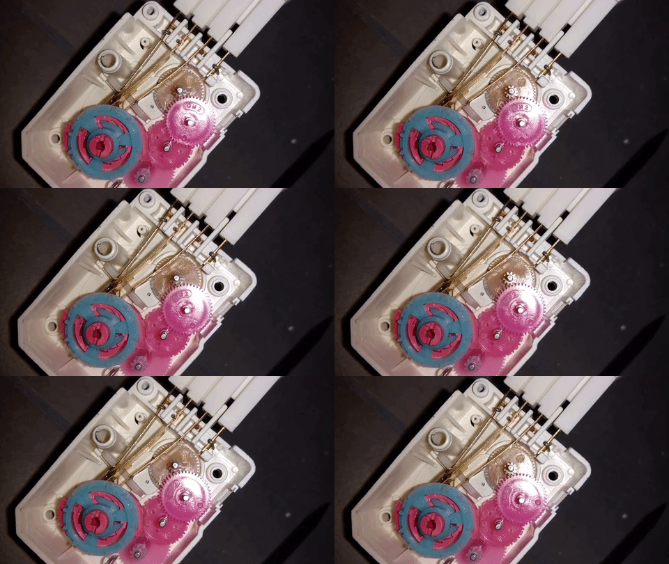
As I suspected, most of the wheels move very slowly, so the noise likely came from the motor cog or the wheel connecting to it. Unfortunately, I couldn’t get a good photo of the motor because it’s hard-wired to the leads of the timer box.
Boxing it back up
I took care to re-seat all of the wheels and make sure they were clean. The higher-speed ones had some light oil on them from the factory that was still mostly intact, so I didn’t add any lubricant.
I had a little scare when the compressor made some effort to start and then gave up with a click. It turns out that the compressor can’t start when the output line is pressurized, and its thermal overload protection was turning it off for trying. After the pressure boiled off through the evaporator, everything started up again, and the ticking sound was gone!
