Thoughts on Sumo 2
14 April 2011
The Sumo is physically complete. I have of course discovered several problems in the design, both in the circuit and the mechanics.
The Circuit
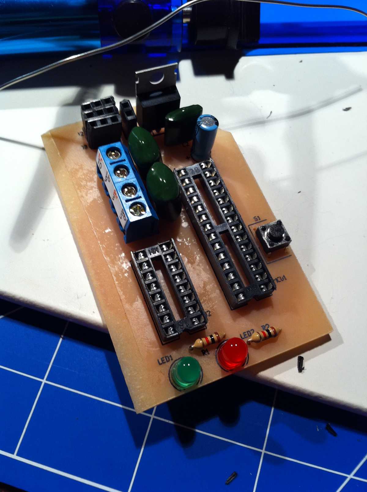
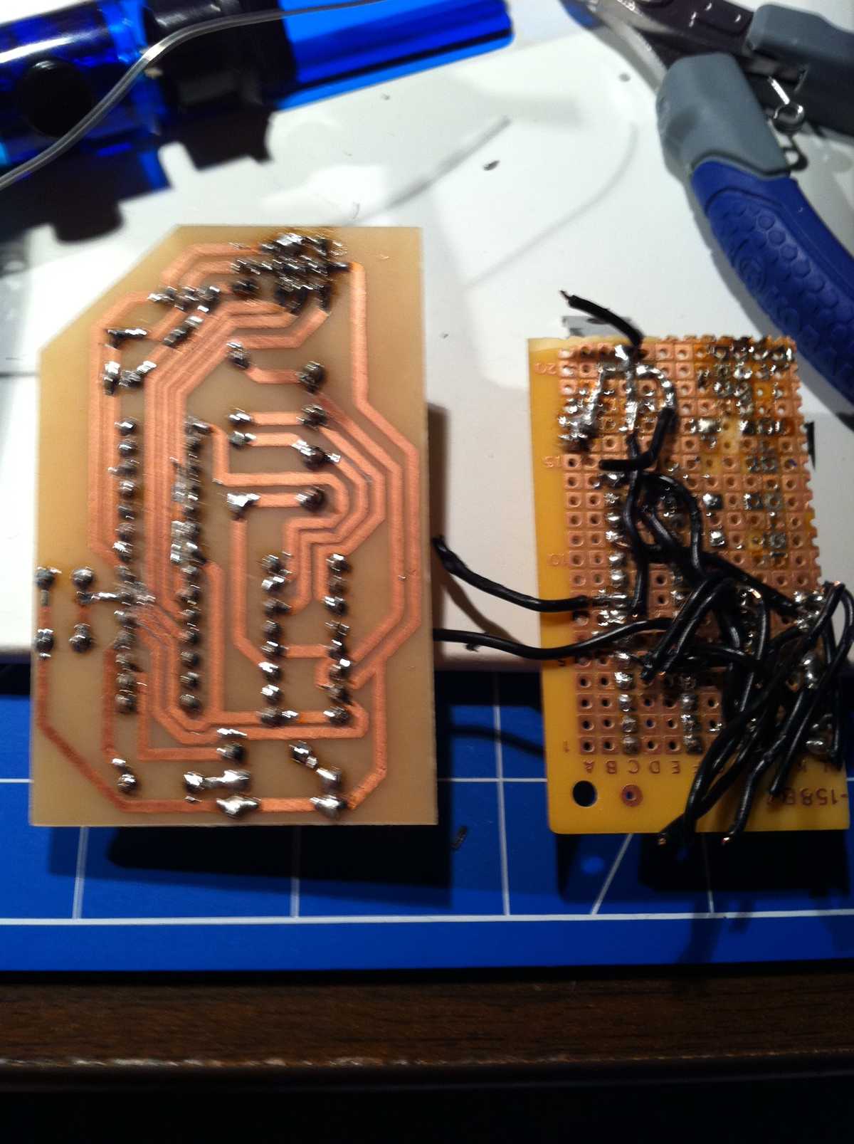
First off, the circuit. In my PCB I had routed some traces that would need jumpers close to other pins. Rather than jumping the neat way, with a via and a component-side wire, I decided to surface-mount the jumpers to the trace side of the board. For next time, I will dedicate some vias for the jumpers, and route my traces farther apart.
I forgetfully connected Arduino D1 to a green status LED. D1 happens to be the serial transmit pin, so my green LED would either blink every time I send serial data, or my controlling the green LED would send spurious serial data. I cut the trace with a razor knife and jumped it to D8, a free pin that happened to be physically near the LED.
The battery input jumper is too close to the 7805 regulator, which needed a heatsink for testing, making it difficult to plug and unplug the power cable and sensors (also nearby). The general number of jumpers was annoying to deal with after a long build on the PCB, especially because the jumpers clutter up the bottom of the otherwise-tidy board.
The Mechanics
My robot is front-wheel drive, to avoid tracking issues associated with the large tolerances in the free wheels. Unfortunately, when the robot pushes against an object with its front shield, it tends to torque backwards about the rear wheels. The result is a lift on the front wheels and a loss of traction. My next bot will have motors in the rear, if not on all fours.
Unfortunately, for this round, I will not be able to change the drive layout in time. The sensors rely on the free space around the front wheels, so running the robot in reverse will not work. I would need to move the motors to the rear-wheel slots, and I don’t think there will be room.

