Gauges: Vintage Analog Computer Monitoring
13 March 2012
I love the look and feel of vintage analog gauges, like those on the instrumentation panels of WWII-era planes and submarines. They have a certain aura of importance and longevity that attracts me. I have been thinking about a wireless hardware add-on that artfully displays my computer’s temperature and CPU usage, and I figured that some of those old gauges would be awesome for this project if I could find them at the right price.
I had actually looked around online for vintage panel meters before, but I was too specific: I was trying to find DC panel meters for voltages under 12V. I recently realized that I could instead choose any of the multitude of DC meters available on eBay, as most of them simply use scaling resistors to calibrate to the ranges on their faces. So, I ordered two that I thought looked cool, for around $20 each.
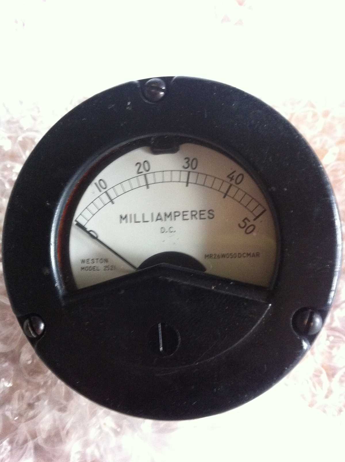
I got the first gauge in the mail today. It’s a “20 mA” DC current meter, with a metal faceplate, solid glass crystal, and a metal housing. It has two screw terminals on the back. It’s also waterproof and ruggedized. Of course, I want it to display CPU temperature and not “DC Milliamperes,” so I immediately started the teardown.
The Teardown
The gauge has a metal face held on by six small machine screws. Removing these, along with the three mounting screws, I exposed the crystal.
The crystal lifts off, though it was a bit stuck down due to years of pressure on the rubber gasket. Prying up gently around the gasket, the crystal easily peeled off and I was left with the exposed inner gauge.
To get the gauge assembly out I had to remove the screw terminal nuts on the back of the unit. Then everything slid out of the housing.
The faceplate was held in place by two hex-headed machine screws. Removing these, I carefully slid the plate out from under the indicator needle. I popped the plate into the scanner, and it was time for a face lift.
The Face Lift
I loved the look of the face that came in the gauge. It just had the wrong label and units. So, I scanned the plate with a flatbed scanner, then cleaned up all around the edges with GIMP, my image editor of choice. I also rotated the face to align it with the program’s grid.
The plate had the word “MILLIAMPERES” across the center, so the first change I made was replacing this text with “CPU TEMP”. I also changed the smaller “D.C.” label to “°C”, and masked out all the numerals with background color.
To find the range of values I needed, I installed “Psensor,” a graphing utility for system vitals monitoring on Ubuntu. Then I opened every application I could, running multiple browsers with videos and music, etc. I wanted to find the maximum temperature of the CPU under normal conditions. It peaked around 88º C, so I decided on 50-100º C for the indicated values on the new faceplate.
Matching fonts as closely as I could, I aligned the new numerals where the old ones had been. I printed a test page, and fortunately it was exactly the right size!
I got out some fancy stationery that happened to closely match the color of the faceplate, and printed my new design on high quality. I cut the design out with a razor knife, and then carefully applied removable double-sided tape across the whole plate. I trimmed away the edges of the tape so it would’t show.
Finally, I applied the new face plate design and smoothed it down gently. Time to reassemble!
The Reassembly
From here the project was simply a matter of working in reverse. The plate when onto the gauge assembly, and both of its screws went back in.
Then I slid the whole assembly into the housing, and applied the (now clean) crystal, followed by the outer gasket and metal face.
Around back, the screw terminal accessories went back on, and it was time to try some electrical experiments.
Calibration
I wanted to find the full-swing current of the gauge. It was labelled “50mA”, but it came with resistors attached in parallel to the screw terminals on the back. I removed the resistors, attaching my multimeter across the gauge terminal. Its resistance mode measured the gauge at precisely 10 ohms.
Next I hooked the gauge to a 1.3V DC power supply in series with an ammeter and a 10K potentiometer. Dialing down the resistance, the gauge made a full swing at almost exactly 5mA. When I am ready to hook it to a microcontroller, there won’t be a problem sourcing such a small drive current. Awesome!
Files
In case you want to try your hand at gauge modding, here are the GIMP files I used: Gauges GIMP Files
