Reverse-Engineering the Phonak Europlug
27 December 2012
My brother uses Phonak hearing aids, and recently the patch cable he uses to listen to music deteriorated so far that only one channel was working. Unfortunately, the cables are $50 new and hard to buy. I decided to try my hand at making a new cable, using top-quality components.
The Old Cable
In my haste, I didn’t photograph the old cable. It was a blue PVC patch cable with a Y-splitter about halfway up, like many earbud cables. The splitter was suspiciously large, a fact that will be important later in this tale. I started by measuring for continuity from the TRS (tip-ring-shaft) connector to the “Europlug” connectors at the hearing aids. It seemed that the cable was completely broken, since no current would flow except in the ground return!
I thought the discontinuity might be somewhere in the cheap cabling along the way, so I cut the Europlugs off (leaving whips for soldering later) and found that the connectors were intact.
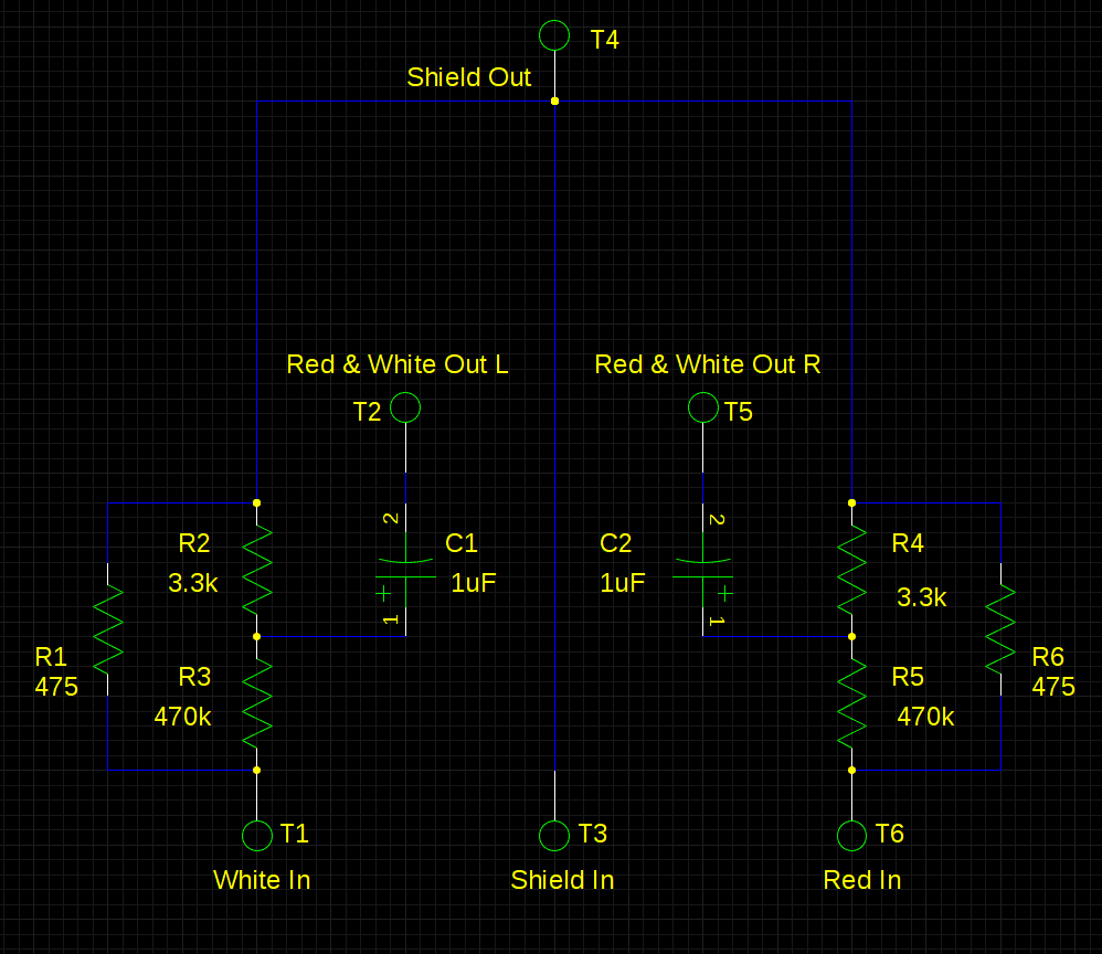
I next checked the TRS end of the cable, and it too seemed okay. The only reason that the cable would not conduct, then, is if it had some sort of AC coupling capacitors for attenuation… I carefully cut away the cast silicone on the larger-than-normal Y splitter and indeed found an attenuator circuit inside. It was formed on a tiny two-sided PCB, but a little trace-following revealed the schematic:
The attenuator turns out to be very important. Without it, headphone audio signals commonly reach up to 2Vpp (peak-to-peak). On the other hand, the low-voltage battery in the hearing aid sets its maximum allowable voltage to around 1.3V. Considering that the ‘aid can function even when the battery is low, and can receive signals from tiny accessory “boots” that act as parasites on the main battery, it makes sense that the signal level can be very tiny. The attenuator in the cable bring the headphone signal down to the order of millivolts, protecting the hearing aid from overvoltage. Without it, even the lowest volume settings would sound horribly loud!
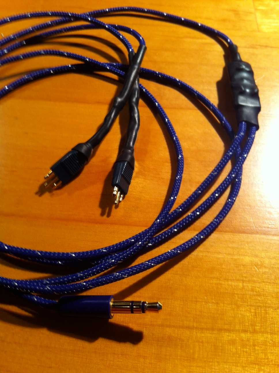
I used the schematic I harvested and the old connectors to build a new, better cable with fancy braided insulation for durability.
Files
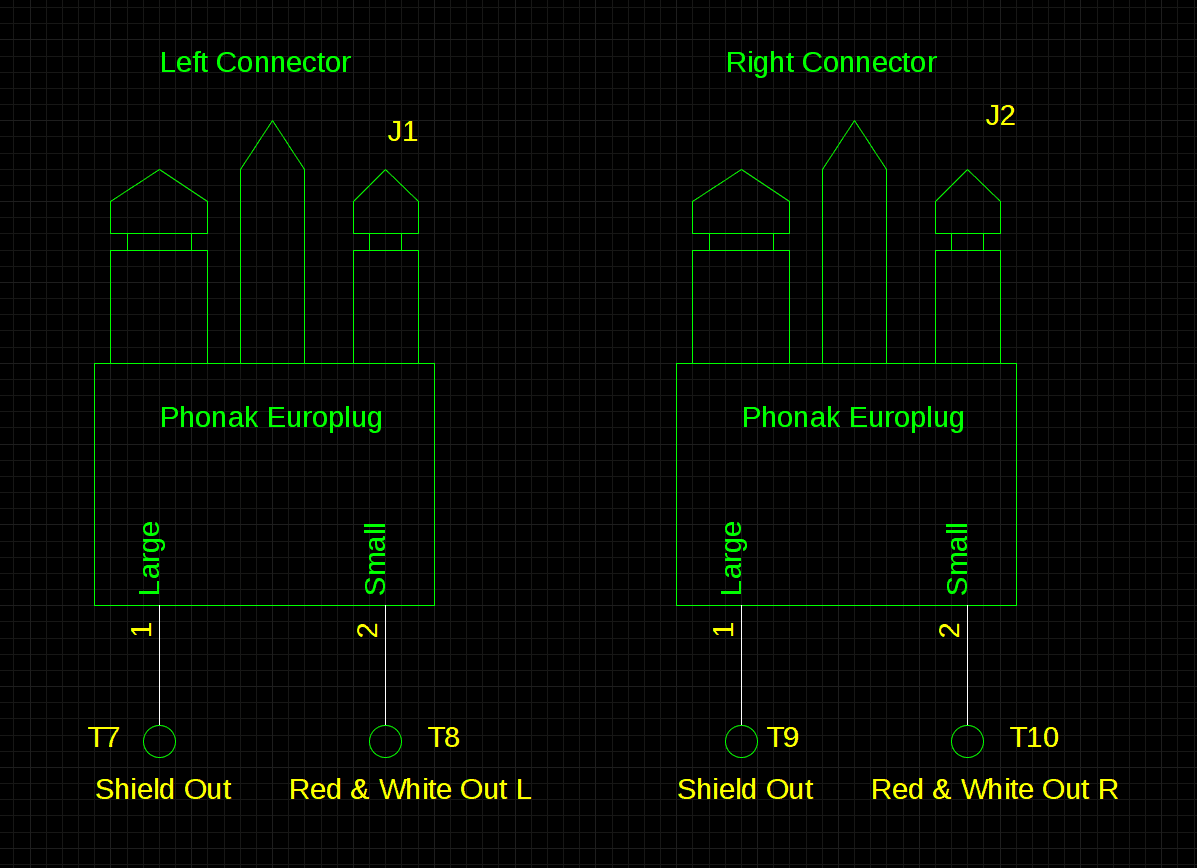
I made a gEDA schematic of the attenuator and connectors, in case anyone needs it. Hack on!


